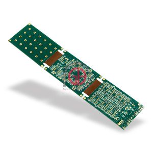
Layer Counts for Rigid Flex PCBs
Rigid PCBs are excellent for many applications, but they have a number of limitations. They can’t be easily bent to adapt to different shapes and spaces, making them difficult to use in some devices. The problem is solved with rigid flex PCBs, which combine the robustness of rigid boards with the flexibility of flex circuitry. These adaptable designs offer more functionality and improved connectivity than rigid PCBs, allowing them to be used in more devices.
When creating a new rigid flex board, the number of layers will have a significant impact on its flexibility. While it’s possible to create a rigid flex pcb with as few as two layers, a higher layer count will allow for more advanced design configurations. For example, a higher-layer design will allow for blind and buried via structures, as well as integrated ZIF connections.

For most applications, a typical range for rigid-flex layer counts is 2 to 6 layers. A higher-layer rigid-flex PCB can also feature a combination of flex and rigid sections, as well as multiple layers of shielding in the flex area. These configurations can provide significant flexibility and improve impedance control.
The Typical Range of Layer Counts for Rigid Flex PCBs
Another consideration when designing a rigid-flex circuit board is the minimum bend radius. This is the smallest angle at which the flex section of the board can be bent without damaging the copper. It’s important to determine this metric early in the design process, as it will affect routing. When determining the bending radius, it’s critical to consider not just the layer count, but also the type of copper that’s being used.
Stiffeners are an important aspect of a rigid-flex PCB, but it’s easy to overlook them during the design process. Overlooking them may lead to stress concentrations, which can cause the PCB to crack and snap under pressure. To prevent this, it’s vital to follow DFM principles and incorporate stiffeners strategically throughout the design process.
It’s important to keep in mind that the more layers you add to a rigid-flex board, the thicker it will be. This is because the manufacturing process requires a certain amount of prepreg thickness for each rigid-flex layer. For example, a 6-layer rigid-flex PCB will require about twice as much prepreg as a 4-layer rigid-flex PCB.
Furthermore, the seamless integration of rigid and flexible substrates enables designers to implement innovative designs that optimize signal integrity and electromagnetic interference (EMI) performance. By strategically positioning components and routing traces, engineers can mitigate signal distortions and minimize cross-talk, ensuring optimal performance in high-speed digital and analog circuits.
When creating a rigid-flex circuit board, it’s crucial to use the right materials for each layer. A common choice is FR-4, which is strong enough to handle the stress of a flex PCB’s dynamic bending and torsional movements. However, you can also choose other options, including a variety of specialty laminates. Just make sure to consult with your manufacturer about the optimal material for your specific application.


+ There are no comments
Add yours